Testing the Linearity of Potentiometers

A potentiometer is a measuring instrument commonly used to measure and control linear motion in industrial-grade machines. They can also be used to control smaller electrical devices. Potentiometers translate a linear, or rotary, displacement into a change in resistance. These are the methods for testing the linearity of a potentiometer.
About Linear Potentiometers
Potentiometers with a linear output have a linear relationship between mechanical travel and output voltage. Linear potentiometers produce a varying resistance output, determined by the displacement or position of a slider or wiper. The linearity of potentiometers involves variable resistors with three leads. Two leads connect to the ends of a resistor, making the resistance between them fixed. The third lead connects to a slider that travels along the resistor, which varies the resistance between it and the other two connections.
Linear potentiometers consume very little power and have proven to be valuable in both aerospace and high-end industrial applications. They feature rugged extruded aluminum housings to withstand harsh chemicals and immersion in oils or water. This durability makes them the preferred choice for robotics, farm equipment, medical equipment, marine equipment, and hundreds of other applications.
About Testing The Linearity of Potentiometers
In order to perform testing methods for the linearity of potentiometers, you will need a few things.
- A DC power supply
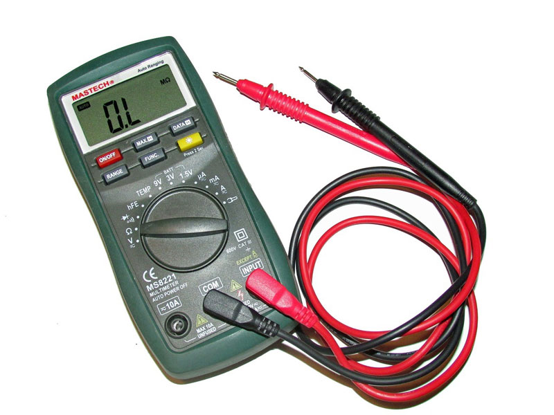
- A DC voltmeter
- A linear potentiometer
- A 4” long insulated copper jumper wire, stripped about ¼” at both ends.
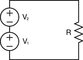
A 3-wire linear potentiometer circuit is a variable voltage divider. As the wiper moves along the resistive element, it provides an output voltage proportional to displacement. The full-scale output voltage is equivalent to the excitation voltage (the amount of direct voltage required to excite a certain field coil). For example, an excitation voltage of ten volts DC would produce an output of zero to ten volts DC.
How to Test the Linearity of Potentiometers
Method for Testing the Linearity of Potentiometers
- Connect the jumper wire to the negative terminal of the power supply.
- Attach the sensor’s positive excitation wire to the positive terminal of the power supply.
- Attach the sensor’s negative excitation wire to the negative terminal of the power supply.
- Connect the positive lead of the DC voltmeter, to the sensor’s signal output wire.
- Connect the negative lead of the DC voltmeter, to the jumper wire that is attached to the negative terminal of the power supply.
- Set the voltmeter to measure DC voltage.
- When testing the linearity of potentiometers, set the DC power supply to 10 volts DC.
With the linear potentiometer fully extended, your voltmeter should display 10 volts DC. And oppositely, with the linear potentiometer fully retracted, the voltmeter should display zero volts DC.
Your Custom Potentiometer Solution
Trust P3 America for custom potentiometer solutions. Source industrial grade, high precision, and reliable products for long-lasting operation. Need OEM support or a custom component? We’ll even customize down to 1 unit.
Contact our experienced, knowledgeable, and USA-based staff today for quick answers to your precision sensor inquiries today.
Recent Posts
-

Features of Motion Control System Components
Defining system requirements with clarity is the first step in selecting motion control system compo …Aug 18th 2025 -
Popular Types of Load Cells for Weighing Applications
One of the most widely used types of load cells is the strain gauge load cell. It’s a transducer th …Aug 15th 2025 -
An Industrial Motion Controller for All Directions
Industrial motion controllers have forever changed the industrial and technological landscape by all …Aug 13th 2025


